J533 Harness Install
⚠️ This wiki is community-maintained. The wiki should NOT be considered "word of comma". Edit suggestions are welcome and encouraged!
| Term | Description |
|---|---|
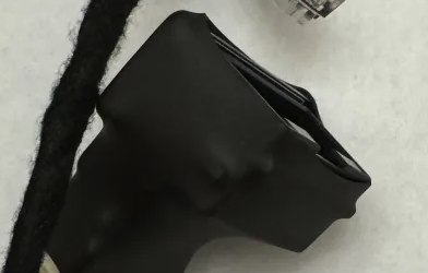
| J533 Harness | On the comma.ai site, it is referred to as the "harness connector". This is the harness you see in the first image below. It has 4 plugs and can be bought from comma.ai. This harness connector is already plugged into the relay, which is why it may be hard to see the white Molex connector. |
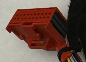
| J533 Connector | This can be a red connector(sometimes black) that is found plugged into the J533 Module usually located in the driver's footwell of specific cars. This is NOT the harness connector you bought from comma.ai. This is already in your car. |
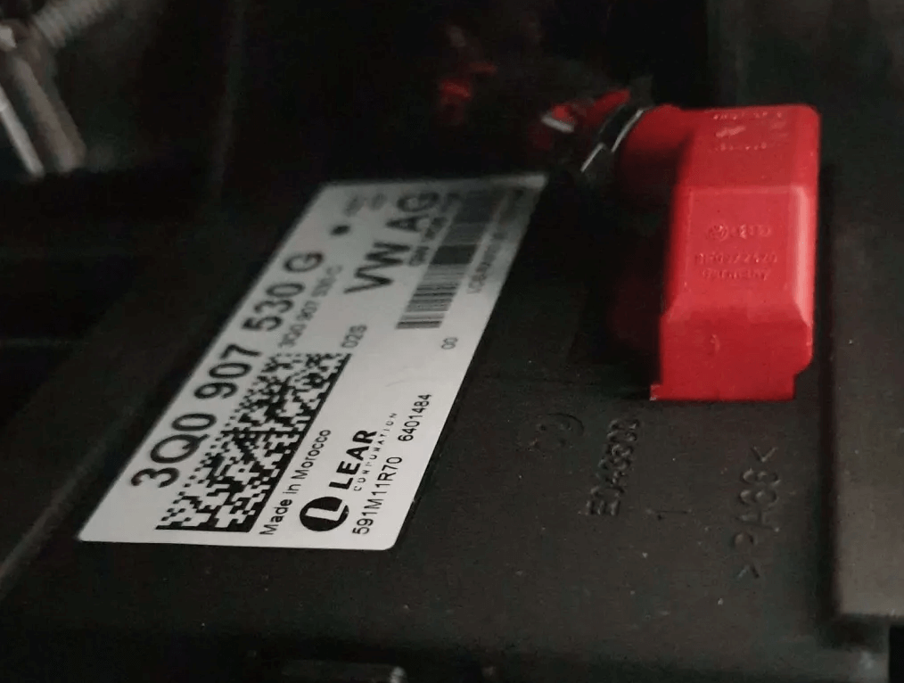
| J533 Module/gateway/can bus gateway module | The gateway is found underneath the steering wheel and above the brake/gas pedal. It typically has some text on it with something that looks like a barcode. There will be a red(sometimes black) connector connected to it. Example images below. |
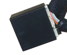
| Relay/harness box | This is the small black box in the picture(B.) below. This is also known as the "harness box" on the comma.ai site. |
The J533 harness has everything necessary for the connection to the car integrated. There's NO need to access the LKAS camera(usually found behind the rearview mirror) or OBD2 port.
Getting To Know Your Wires
This image is here for reference when going through the installation process. Having another tab open or a device handy with this part of the guide open can help go through the installation process quicker.
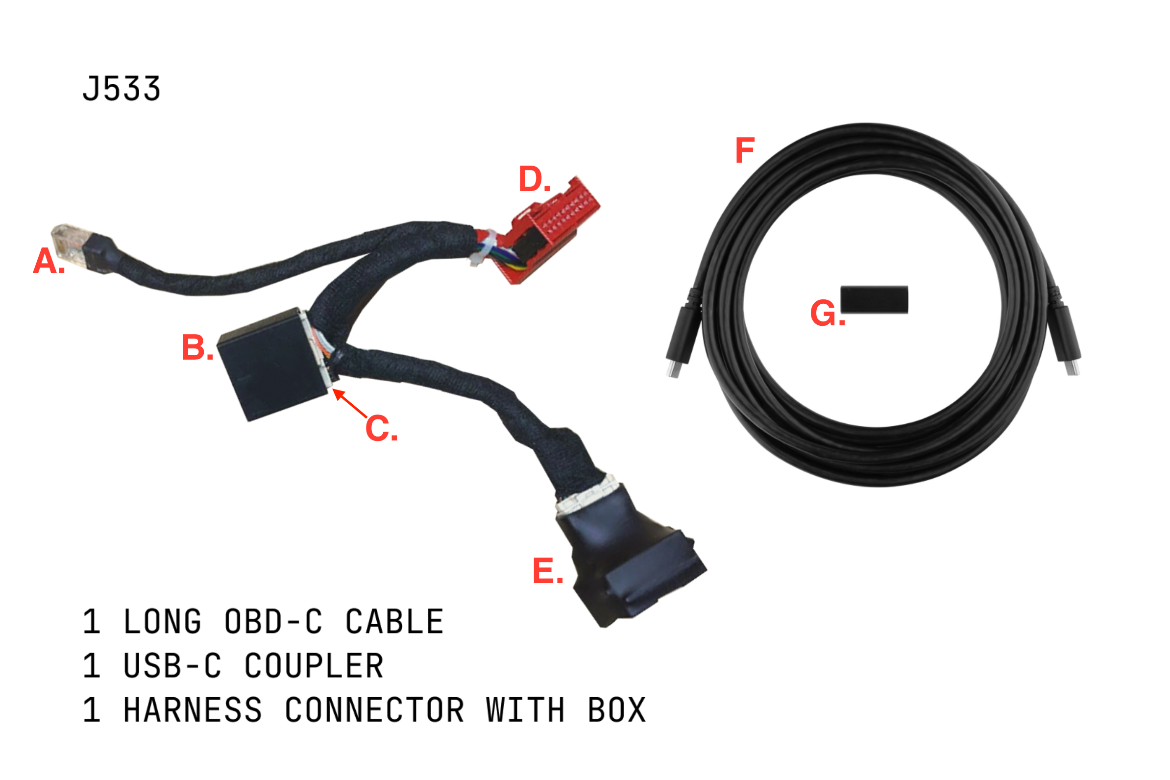
A) RJ45 connector: This HAS to be plugged into the other side of the relay. This will sometimes be found already plugged into the relay. If it is, leave it plugged in. If not, plug it into the relay.
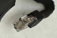
B) Relay: This is the small black box. This black box(aka harness box) will have a spot to connect the Rj45 and USB-C cables that are provided. In the photo above, the relay is already connected to the white Molex connector from the harness connector.
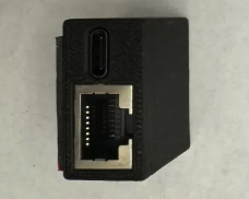
C) White Molex connector: This should already be plugged into the relay(black box). Leave it plugged in.

D) Female J533 plug: This will be the end that plugs into the car's J533 Module/gateway.
E) Male J533 plug: This will be the end that gets connected to the car's J533 connector.
F) Long OBD-C Cable: This will connect to the relay(black box)and the other end will have the USB-C coupler which then connects to the provided comma 3x USB-C cable.
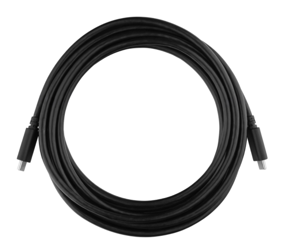
G) USB-C Coupler: This connects to the end of the long USB-C cable that reaches the comma device.
Are you missing something?
If you do not have the same items above, the installation will not work. You will need all the items listed above to install your comma device with a J533 Harness.
Ways to identify the J533 Module
- Look for a Red or Black Connector: The J533 module usually has a distinctive red or black connector plugged into it. This connector is the interface point for the J533 wiring harness
- Inspect the Location: If you're in the driver's footwell area, look for a module mounted on or near the firewall, close to where the wiring enters the cabin. It may have labels or markings indicating its designation as the Gateway or J533 module.
- Compare with Reference Images: You can compare the module in your vehicle with reference images available online or in this installation guide to confirm if it matches the appearance of a J533 module.
If you're still unsure whether the module you're looking at is the J533 module, you can try reaching out on the #volkswagen-audi-skoda Discord channel.
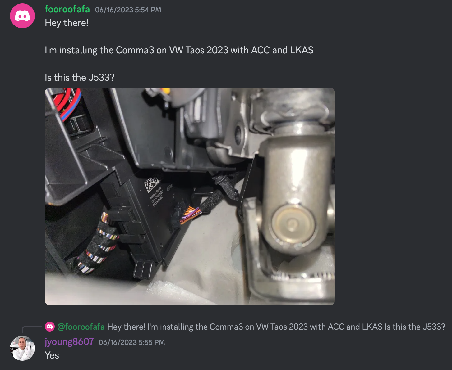
Example Discord message
Please provide the following in the Discord chat:
- A clear picture of what you see. Provide multiple if needed.
- What comma device is being installed?
- Car make
- Car model w/ year
- Does it have ACC and LKAS? (including this part is not required but is nice to have)
How Your J533 Connector and J533 Module Looks Like
Below are pictures to help you get familiar with what to look for. For most cars, you will be looking for a red connector but sometimes they can be seen as a black connector already plugged into the J533 Module.
Audi A3 8V 2018
](https://files.readme.io/15079f9-Screenshot_2024-04-19_at_8.35.56_PM.png)
Source: Discord Chat
VW Golf Sportsvan
Source: Discord Chat
VW Taos 2023
](https://files.readme.io/a3e19c4-Screenshot_2024-04-19_at_8.37.10_PM.png)
Source: Discord Chat
VW Tiguan S 2024
](https://files.readme.io/529ac05-b53050f-image_1.png)
Source: Discord Chat
VW E-Golf 2020
](https://files.readme.io/e76fdf2-9794304-Screenshot_2024-04-12_at_11.52.28_AM_1.png)
Source: Discord Chat
VW Atlas 2023
](https://files.readme.io/7c7c37e-Screenshot_2024-04-19_at_8.39.14_PM.png)
Source: Discord Chat
VW Arteon 2021
](https://files.readme.io/fe0f6fb-Screenshot_2024-04-12_at_12.23.39_PM.png)
Source: Discord Chat
Can you spot where the J533 connector and module is?
The picture below shows VW Tiguan 2020. Stop reading here if you don't want the answer. If you said the J533 is at the top left of the photo with the red cable, you are correct! 👍
](https://files.readme.io/dd908ac-Screenshot_2024-04-12_at_12.29.15_PM.png)
Source: Discord Chat
All Wired Up
](https://files.readme.io/8f300ff-image.png)
Car: Audi A3/S3 2016 \ Source: Discord Chat
The end product of how all the cables should look when connected is the picture above. We will be going step by step on how to get the same results. If you read the full guide and follow the instructions you'll be alright. If anything looks wildly different, and you start to panic. Breathe, and ask some questions on Discord in the #volkswagen-audi-skoda channel. Lots of people in there went through the same process you did and can help with the hurdles you've encountered. Be sure to read Search Before You Ask 🔗. Reading this will help you ask better questions that get more people to assist in whatever problem you may have during the installation.
How To Install J533 Harness:
Reminder: The J533 harness has everything necessary for the connection to the car integrated. There's NO need to access the LKAS camera(usually found behind the rearview mirror) or OBD2 port.
Step 1: Turn off the car
Ensure the car is off and move the driver seat as far back as you can to give you the most bottom floor room possible
Step 2: Ensure that RJ45 is connected to the Harness Box/relay

RJ45

Harness Box/relay
This can sometimes be found connected already. If not, connect the RJ45 to the relay.
Step 3: Ensure that White Molex is connected to the Harness Box/relay
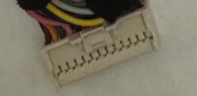
White Molex connector
If the White Molex is not connected, go to the opposite side of where you plugged the Rj45 into the Harness Box/relay and connect the White Molex connector there. The picture above shows the White Molex connected to the Harness Box/relay
Step 4: Connect the long OBD-C cable to the Harness box/relay

Long OBD-C

Harness box/relay
Both ends of the OBD-C cable are the same so grab either ends and connect to the relay.
Step 5: Check if you need to remove the panel underneath
Run your hand below the dash to see if there is a panel to remove
Step 6: Remove the panel in the way
Most panels can be removed with a Torx Screw Set. If there isn't a panel, move to the next step.
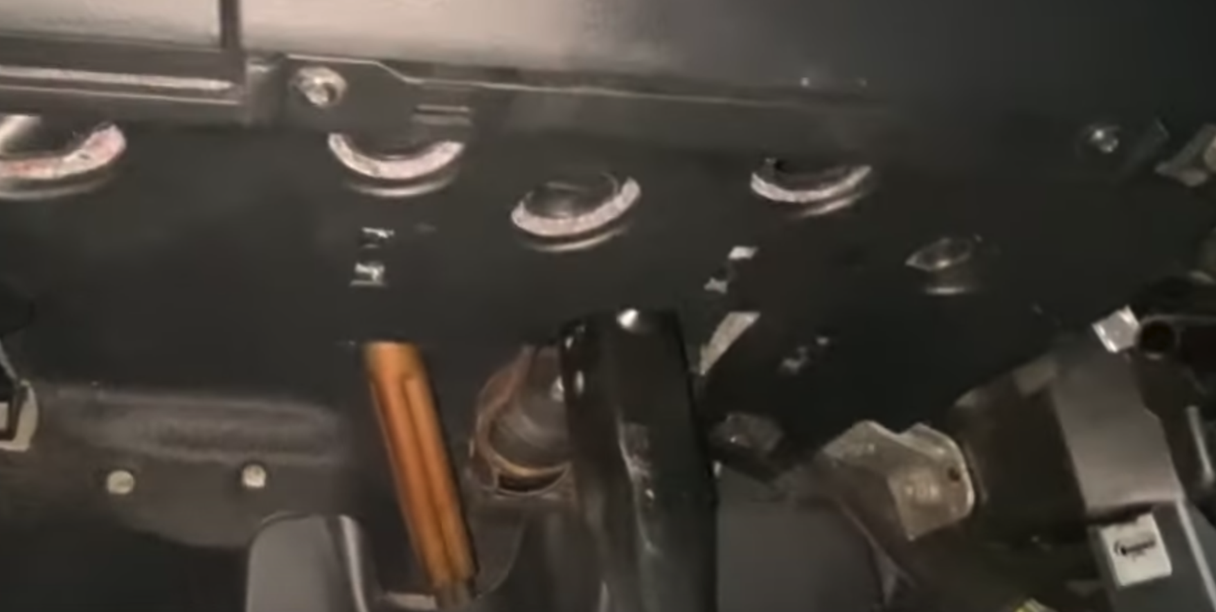
Step 7: Take a photo with your phone
After removing any panels, the best way to find the module with the J533 connector is to lay down your phone under the pedals in the middle of the footwell as far back as the flat area goes, point some light upwards, and take a picture directly upwards.
Step 8: Locate J533 connector and module/gateway
Source: Discord Chat
If you have read this whole guide you would have already seen some examples of what to look for. Click here to go back to more examples. Locate the J533 connector and module/gateway in the photos or videos you took.
Still cant find it? If you still can't find where the J533 connector and module/gateway is, send the pictures you took and follow the instructions from here.
Step 9: Lay on your back
Lay on your back next to the gas and brake pedal after locating it from the photos you took. Laying on your back will help you locate the module/gateway faster and give you the arm reach you might need. Depending on where your J533 connector and module/gateway are located laying on your back may be needed.
Step 10: Disconnect the car's J533 connector from module/gateway
](https://files.readme.io/e4b8638-Screenshot_2024-04-12_at_1.50.00_PM.png)
Source: Youtube
Make sure to firmly press down the latch when removing the plug. Taking photos or videos to see where the latch is or where you need to press down on the connector can help find where to press down to disconnect the cable.
Step 11: Plug in disconnected J533 connector into the J533 Harness
](https://files.readme.io/15034b7-Screenshot_2024-04-12_at_1.53.52_PM.png)
Source: Discord Chat
Plug the disconnected J533 connector into the male J533 plug(from J533 Harness). The red cable is the disconnected J533 connector. This can also sometimes be a different color. The black cable in the image is the male J533 plug.
Step 12: Connect female J533 plug into J533 module/gateway
](https://files.readme.io/f3c5068-Screenshot_2024-04-12_at_1.56.23_PM.png)
Caption: Discord Chat
Plug the female J533 plug(red cable) from the harness connector into the J533 module/gateway(black box with the barcode sticker in the picture).
Step 13: Does your connections look similar to this?
Car: Audi A3/S3 2016 \ Source: Discord Chat
If you said yes. Nice job! You are halfway there. Time to route the OBD-C cable!🎈
Cable Management Guide
This section will review the best options for routing the long OBD-C cable to reach your comma device on the windshield. If there are cleaner, easier routing solutions than this, give me a ping!
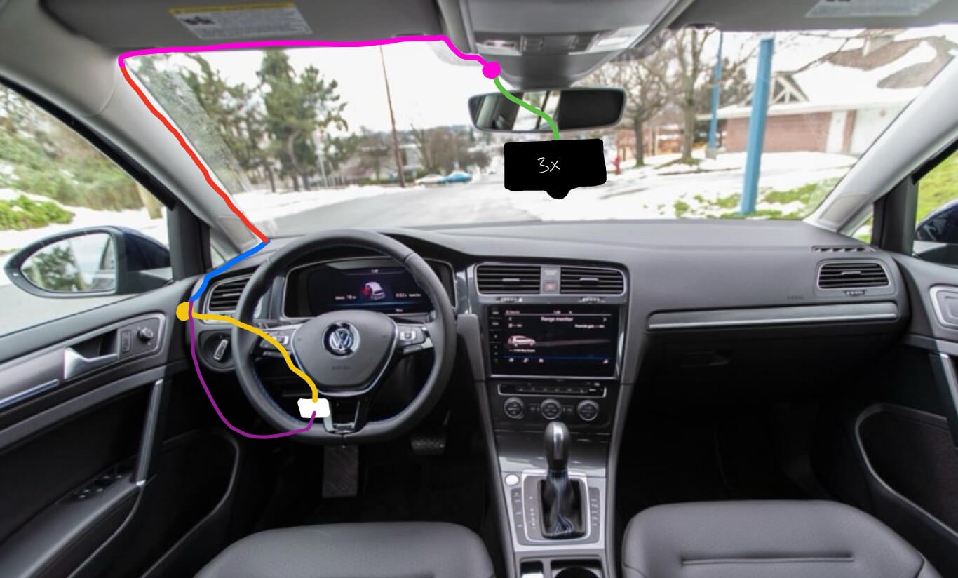
Routing Diagram

| Color | Description |
|---|---|
| White Box | This is the general location of where the J533 module. |
| Yellow Line | The OBD-C cable running through the fuse box area traveling left toward the driver door. |
| Yellow Circle | There should be a removable plastic panel that the OBD-C cable can come out of. Run the OBD-C cable through the cracks of this panel. |
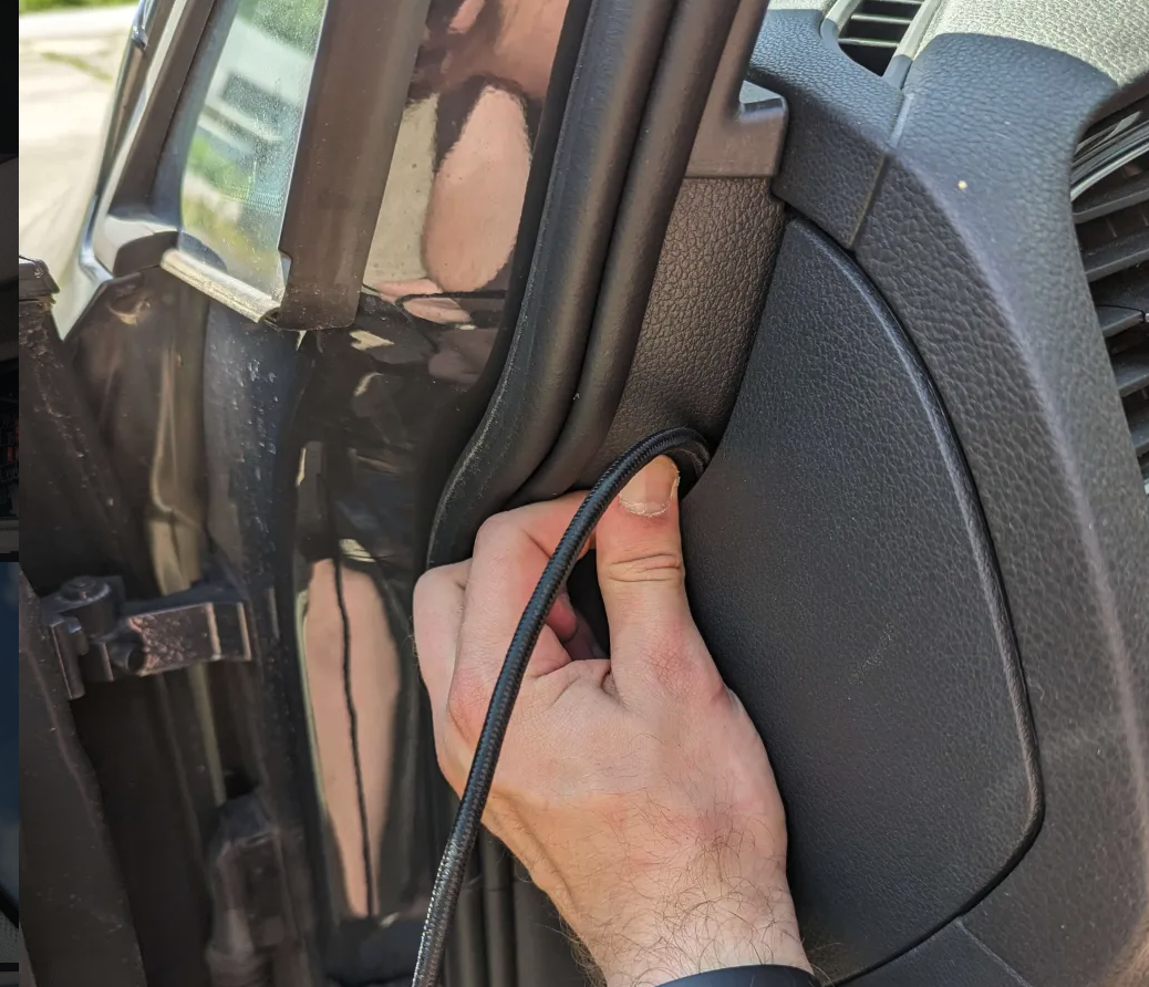
| Blue Line | the part of the cable will run under the weather stripping near the door until it gets to the A-pillar. Once you reach the A-pillar, route the cable to reach the position of the red line. The cable should not cross on top of the airbag! |
| Red Line | This part of the cable should sit between the windshield and the airbag. Find factory wiring and route the cable where the factory wires are running. DO NOT put wire on top of the airbag! |
| Pink Line | This part of the cable will be tucked underneath the edge of the headliner. |
| Pink Circle | USB-C coupler that is included when you buy the OBD-II harness. This USB-C coupler will connect the 1.5ft right-angle OBD-C cable to the long OBD-C cable that comes with the OBD-II Harness from comma. |
| Green Line | The 1.5ft right angle OBD-C cable that is included when you buy a comma 3X. |
Step 1: Grab the OBD-C cable
- Grab the other end of the OBD-C cable NOT connected to the Harness Box/relay
- Don't put the USB-C coupler until the cable is closer to the comma device
Step 2: Bring wire through the fuse box
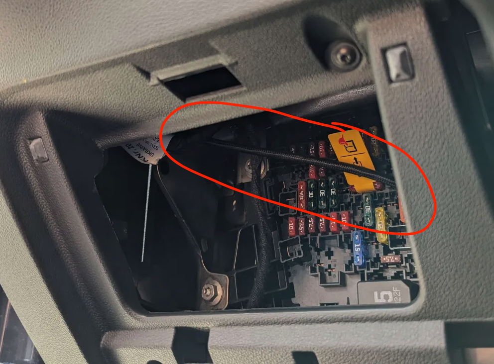
- Bring the end of the OBD-C cable through the fuse box
- There should be another opening on the other side for the cable to slip through
Step 3: Slip the cable through the back crack
Grab the OBD-C cable and push it through the back crack.
Step 4: Ignore the previous 2 steps IF...
- If your car does not have the side opening shown in the previous step, skip those steps
- Route the cable(purple line) underneath the fuse box then up to the bottom of the blue line as shown above. The cable can be tucked into the weather stripping near the door.
- If you successfully did the previous 2 steps then ignore this step
Step 5: Removing A-pillar
It's important not to restrict the airbag in case of an accident. Do not place wires on top of the airbag.
⚠️ Make sure to read A-pillar Wire Routing 🔗. This is an essential step to ensure the wire is routed in the safest way possible. After reading A-pillar Wire Routing return to this guide and proceed to the next step.
Step 7: Tuck the remaining wire
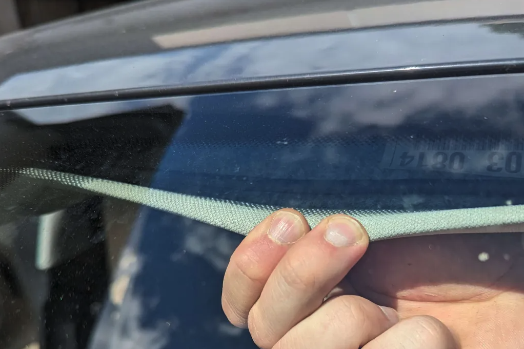
Last time you will be tucking in wires. This part is the pink line from the diagram. Peel open the edge of the headliner and tuck the wire in. Tuck the wire across the windshield until it reaches the comma device.
Step 8: Grab USB-C Coupler
Connect the USB-C coupler to the end of the OBD-C cable.
Step 9: Connect comma Device Cable
- Grab the included cable that came with the comma device and plug the angled end into the device.
- Grab the other end and plug that into the OBD-C cable that has the USB-C coupler
Step 10: Turn On Car

When you turn on the car the comma device should power up automatically. Your wire routing should look like the above diagram. The blue and pink line shows the 2 options for that area.
Step 11: Give yourself a high-five! 🏁
Nice job! You have installed the necessary hardware to use your comma device with a J533 harness! Continue to the next part where you learn how to install software into your comma device.
GitHub Community Wiki
Check out the Community Wiki for Volkswagon.
Have feedback?
If any steps were incorrect or could have better pictures/descriptions for that step, send them my way. Give me a ping on Discord and if the suggestions make sense I will update the guide.