OBD-II Harness Install
⚠️ This wiki is community-maintained. The wiki should NOT be considered "word of comma". Edit suggestions are welcome and encouraged!
Who is this guide for?
This is for certain GM vehicles that have ACC, LKAS and use an ASCM (Active Safety Control Module), this module must be bypassed to allow OpenPilot to function.
In this guide, we will be using a Chevy Volt 2017-2018. If your GM vehicle has a similar build and tech this guide should work for you. Be sure to order your L&P Harness kit with GM light switch asap because it takes about 30 days for it to get made and shipped out.
What is an ASCM?
ACSM stands for Active Safety Control Module. It is the car's computer/module that does sensor fusion from the Radar and Camera to create ACC and LKAS messages to PCM (powertrain control module). The ASCM Is typically located in the trunk.
In certain GM vehicles that use an ASCM (Active Safety Control Module), this module must be bypassed to allow OpenPilot to function. This is the only vehicle “modification” needed and it's easily and completely reversible. We will not need the vehicle’s camera module behind the rearview mirror during this installation. Besides the ASCM bypass, the only other connection required is to the OBD-II port in the driver's footwell.
How do you know if your car has ASCM?
](https://files.readme.io/4bfab10-Screenshot_2024-04-18_at_12.16.22_PM.png)
Source: Dauv
The ASCM will be a box that has a label on it. It will look similar to the black box above.
General location of ASCM
](https://files.readme.io/0161f42-Screenshot_2024-04-18_at_12.22.40_PM.png)
2018 Escalade - Source: Discord
](https://files.readme.io/cd4e80e-Screenshot_2024-04-18_at_12.27.16_PM.png)
2017-2018 Chevy Volt - Source: Dauv
The car's ASCM is typically located on the driver's side of the vehicle in the trunk area.
Drawbacks of Disabling ASCM
Disabling the ASCM has the following drawbacks:
- No AEB (automatic emergency braking). The stock system will slow your vehicle by ~20 mph if you are going to run into something in front of you. It won't prevent you from crashing into something if you're driving above 30 mph, but it'll at least slow you down before impact.
- Stock ACC (cruise control) does not work, but OpenPilot replaces this functionality pretty well. Currently, OpenPilot doesn't work as well as stock ACC, but it will improve.
- Stock LKA (lane keep assist) does not work. The stock functionality is very unreliable in any case. OpenPilot will do a better job of this when it's active.
- No parking distance warning front or rear. No auto-braking if you're going to back into something that the car would normally detect (like a trash can).
- No traffic crossing warning when backing up out of a parking spot.
- The backup camera works, but the guidance lines flash on and off rapidly.
- No more auto high-beam function.
- If the simplest ASCM bypass method is left connected, it will drain the battery by powering the radar unit 100% of the time. Drawing power from another location with "key-on" power will prevent battery drain.
The above was from a Discord chat from @qeggleston, he linked a document he wrote that talks about some notes about the install process.
Note about L&P Harness (w/ GM lightswitch)
Keep in mind that the site says "Please allow for up to 20 days for the harness to be shipped."A chat on Discord says they waited 28 days. Make sure to buy this as soon as possible, to decrease the wait time to install comma device.
Also, read the item description on the site to ensure your car is compatible. If you have more questions make sure to read first Search Before You Ask before asking in the #gm Discord Channel for help.
The L&P Harness Kit above should include:
- ASCM Harness
- OBD2 Splitter
- GM Light switch with selector switch
- Additional fuse circuit
GM Light Switch or Without?
There are 2 options for the L&P Harness. Both options deliver the same functionality with certain trade-offs. In this guide, we will be using the L&P Harness with GM light switch.
With GM Light Switch
- More aesthetically pleasing. It looks like it belongs to the car.
- Easier to reach, which may be helpful for certain forks to do quick reboots while driving
- Con: It takes extra steps to install, people on Discord say the extra steps can be tedious
- Con: More expensive
Without GM Light Switch
- Easier to install, no need to take off the stock light switches
- Cheaper
- Con: Harder to reach if you want to do a quick reboot
How to Install the OBD-II Harness
If anything looks wildly different, and you start to panic. Breathe, and ask some questions on Discord in the #gm channel. Lots of people in there went through the same process you did and can help with the hurdles you've encountered. Be sure to read Search Before You Ask🔗. Reading this will help you ask better questions that get more people to assist in whatever problem you may have during the installation.
Helpful Videos and Links:
These are helpful videos and links on which this guide is based heavily. In some steps, I will refer to the videos below with a timestamp. If there are any steps you feel like I am missing that would be valuable to add, let me know, and if it makes sense I will add it.
Step 1: Check for necessary tools and cables
Things you will need:
- comma device w/included mounts and cables
- OBD-II Harness from comma (select your vehicle)
- L&P Harness kit with GM light switch
- Long needle nose pliers (to remove multiple fuses)
- Trim removal tools
- Socket wrench w/7mm attachment (to remove 7mm screws)
Step 2: Make sure the vehicle is off
The vehicle must not be turned on during installation.
Step 3: Lower back seats
](https://files.readme.io/da1d530-Screenshot_2024-04-22_at_9.12.54_AM.png)
Source: richiejeep
Pull the lever located at the top of the seat near the headrest. Fold the back seats down for the whole installation process.
Step 4: Remove carpet liner
Left up the top carpet liner and fold it over. Then remove the rest of the carpet that is held down by velcro. Place the carpet liner on the folded back seats or in a place that wouldn't get in the way.
Step 5: Remove clips/screws from foam trunk liner
](https://files.readme.io/f004a9b-Screenshot_2024-04-17_at_6.20.36_PM.png)
Source: Dauv
After removing the carpet liner you should see this, or something similar. Use a flathead to unscrew & remove 3 plastic clips(red circles) and unscrew the plastic bit(orange circle) holding the tow hook.
Step 6: Remove foam trunk liner
](https://files.readme.io/13bd9a1-Screenshot_2024-04-17_at_6.25.42_PM.png)
Source: Youtube - WatchJRGo
Lift the foam liner with one hand grabbing the middle and the other hand at the edge of the foam trunk liner as shown in the picture. You will be tilting the end closest to you up first then, using both hands lifting up to remove the liner. Put the foam trunk liner in a safe place that is out of the way.
Step 7: Locate and open the rear fuse box
](https://files.readme.io/ad31296-Screenshot_2024-04-17_at_6.45.43_PM.png)
Source: Dauv
Look for the black box circled in red. Take off the cap to expose the rear fusebox.
Step 8: Remove fuse #19
](https://files.readme.io/efa9c33-Screenshot_2024-04-17_at_6.50.06_PM.png)
Source: Lee & Paulding
- Use needle nose pliers to remove fuse #19(green circle). Grab the fuse from the top and pull up. Place the fuse in a safe place.
- Removing fuse #19 and avoiding turning on the vehicle prevents the computer from throwing a code. This is done to prevent unwanted communication that might throw a check engine light. However, due to how the Volt is programmed, nothing is actually “turned off”. If a trouble code were to show, delete it with any OBD2 scanner and it would go away after a few cycles of ignition
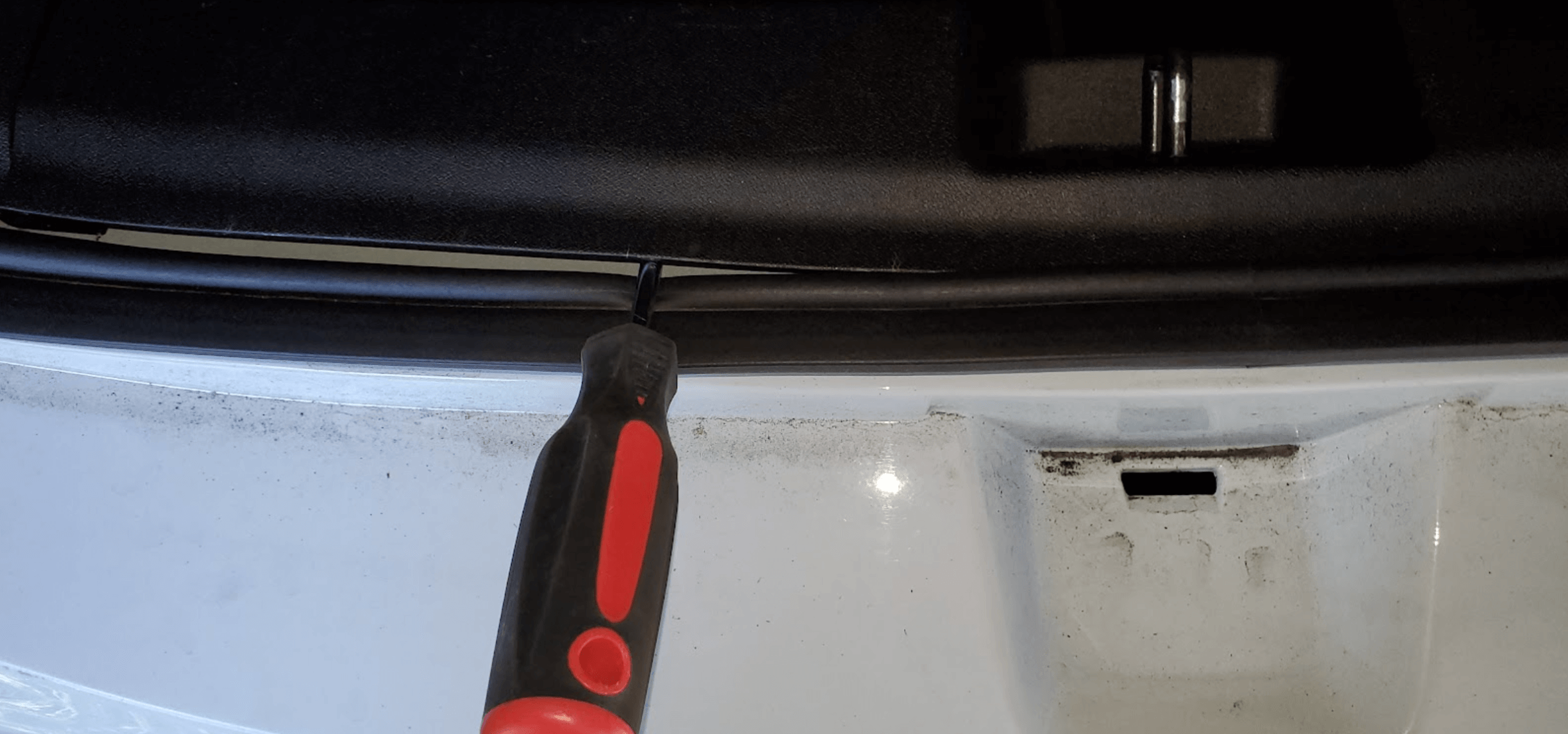
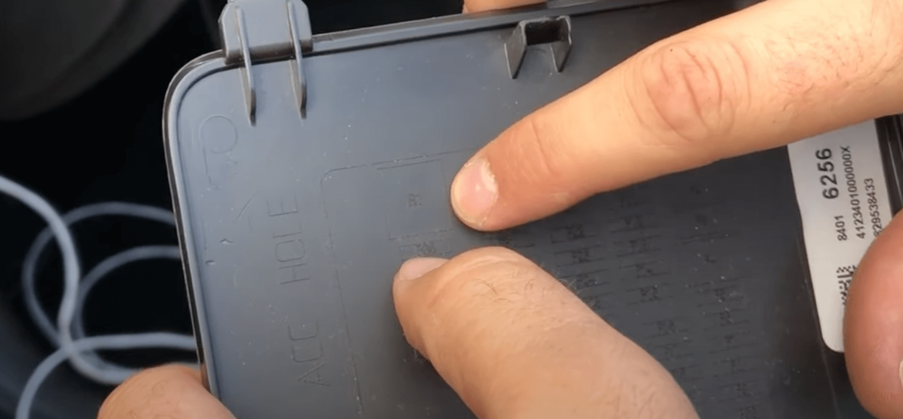
Step 9: Trunk latch plastic piece
](https://files.readme.io/cb09437-Screenshot_2024-04-17_at_7.20.31_PM.png)
Source: Youtube - Atari Guy
Remove the plastic piece under the latch using a removal tool or screwdriver. Wedge the tool like the photo to pop the piece off from under the latch.
Step 10: Remove trunk latch panel
](https://files.readme.io/d8cacce-Screenshot_2024-04-17_at_7.37.24_PM.png)
Source: Youtube - WatchJRGo
To remove the piece above we will need our removal tools. Several clips at the top and bottom are holding onto this piece.
Source: Dauv
- Wedge a removal tool (or screwdriver) between the weather strip and the panel near the trunk latch.
- Apply pressure toward the front of the car. Start on one side then move on to the next. You will hear a loud pop when the clips come loose.
Step 11: Luggage hooks
](https://files.readme.io/b2bbed2-Screenshot_2024-04-17_at_8.08.07_PM.png)
Source: Dauv
- On the left and right side of the trunk walls, you will find these luggage hooks.
- Use your hand to unscrew them off.
Step 12: Locate cargo hooks
](https://files.readme.io/f5c8a14-Screenshot_2024-04-17_at_8.12.36_PM.png)
Source: Youtube - Atari Guy
- Find the cargo hooks on the left and right side of the trunk.
- Once found adjust the hook so it sticks out and points towards the front.
Step 13: Remove cargo hooks
](https://files.readme.io/c9deb3c-Screenshot_2024-04-17_at_8.20.01_PM.png)
Source: Youtube - Atari Guy
Use your fingers to tuck under the plastic cap to pop off the plastic cap under the cargo hook. Repeat this process for all the cargo hooks on the left wall. There should be 2 or 3 of them.
](https://files.readme.io/ba6732c-Screenshot_2024-04-17_at_8.40.32_PM.png)
Source: Youtube - Atari Guy
If you are having trouble removing the plastic cap, use your removal tool to wedge in between the bottom to pop it out, as shown in the photo.
Step 14: Removing the top white panel of the left wall
](https://files.readme.io/f37236a-Screenshot_2024-04-18_at_10.21.31_AM.png)
Source: Youtube - Atari Guy
Remove the top white panel before removing the bottom half. This wall is located on the driver's side(left wall) of the car. You can refer to Atari Guy or WatchJRGo video to understand what side.
](https://files.readme.io/fb0b59f-Screenshot_2024-04-18_at_10.25.11_AM.png)
Source: Youtube - Atari Guy
Pull back the weather stripping above the white panel. Wedge the trim removal tool like the above to pop out the white panel. You will be doing this starting on the side closest to the trunk moving your way towards the front. Refer to the timestamp 3min 34sec of Atari Guy removing the panel.
](https://files.readme.io/f764d50-Screenshot_2024-04-18_at_10.28.09_AM.png)
Source: Youtube - Atari Guy
Above is the underside of the panels with the clips. There should be 3-5 clips holding down this white panel. Some places on this white panel may be difficult to pop off. You may need to use a bit of force to pop off the piece.
Step 15: Black wall panel
](https://files.readme.io/999ae81-Screenshot_2024-04-17_at_9.02.24_PM.png)
Source: Youtube - WatchJRGo
The next focus is going to be removing this left wall panel. The white top and black bottom are separate plastic pieces. The white top should have been removed from the previous step. Now we will remove the bottom black panel.
](https://files.readme.io/14e96be-Screenshot_2024-04-18_at_11.07.30_AM.png)
Source: Youtube - Atari Guy
Once the white panel is removed you will be exposed to what you see in the red circle above. Find a place to grip the black panel in the red circle to then pull out enough of the black panel where you can see the exposed metal of the vehicle.
There should be about 3-4 clips holding the black panel down. You do not need to completely remove the panel but you do need to open it enough to get access to whats under it.
Step 16: Pull open black panel
](https://files.readme.io/b7eae0b-Screenshot_2024-04-18_at_11.16.37_AM.png)
Source: Youtube - WatchJRGo
Grab the end of the black panel to open it enough to show what is under it. Open it enough where you can see and put both arms through it, as the photo above shows.
Step 17: Locate the ASCM
](https://files.readme.io/4bc8c7e-Screenshot_2024-04-18_at_12.16.22_PM.png)
Source: Dauv
- You should see the ASCM(Active Safety Control Module) once you open up the black panel. It is usually a box with a label on top.
- Where the red circle is, will be the cable we disconnect
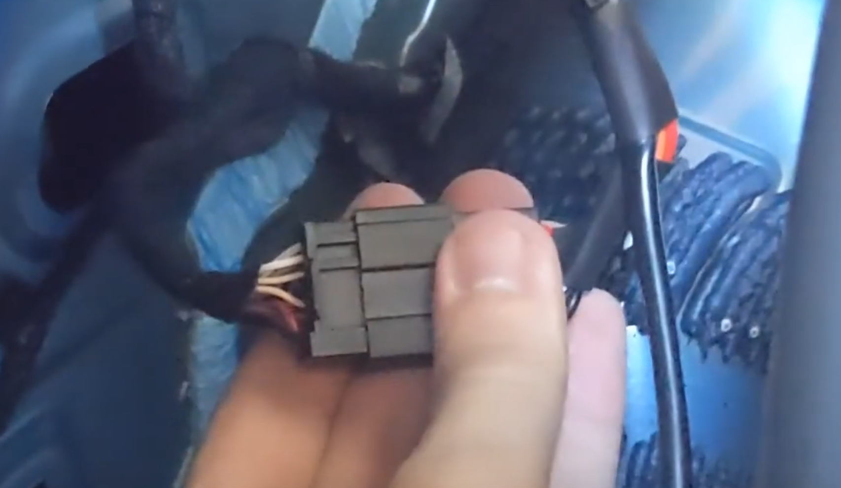
Step 18: Disconnect the top cable of the ASCM
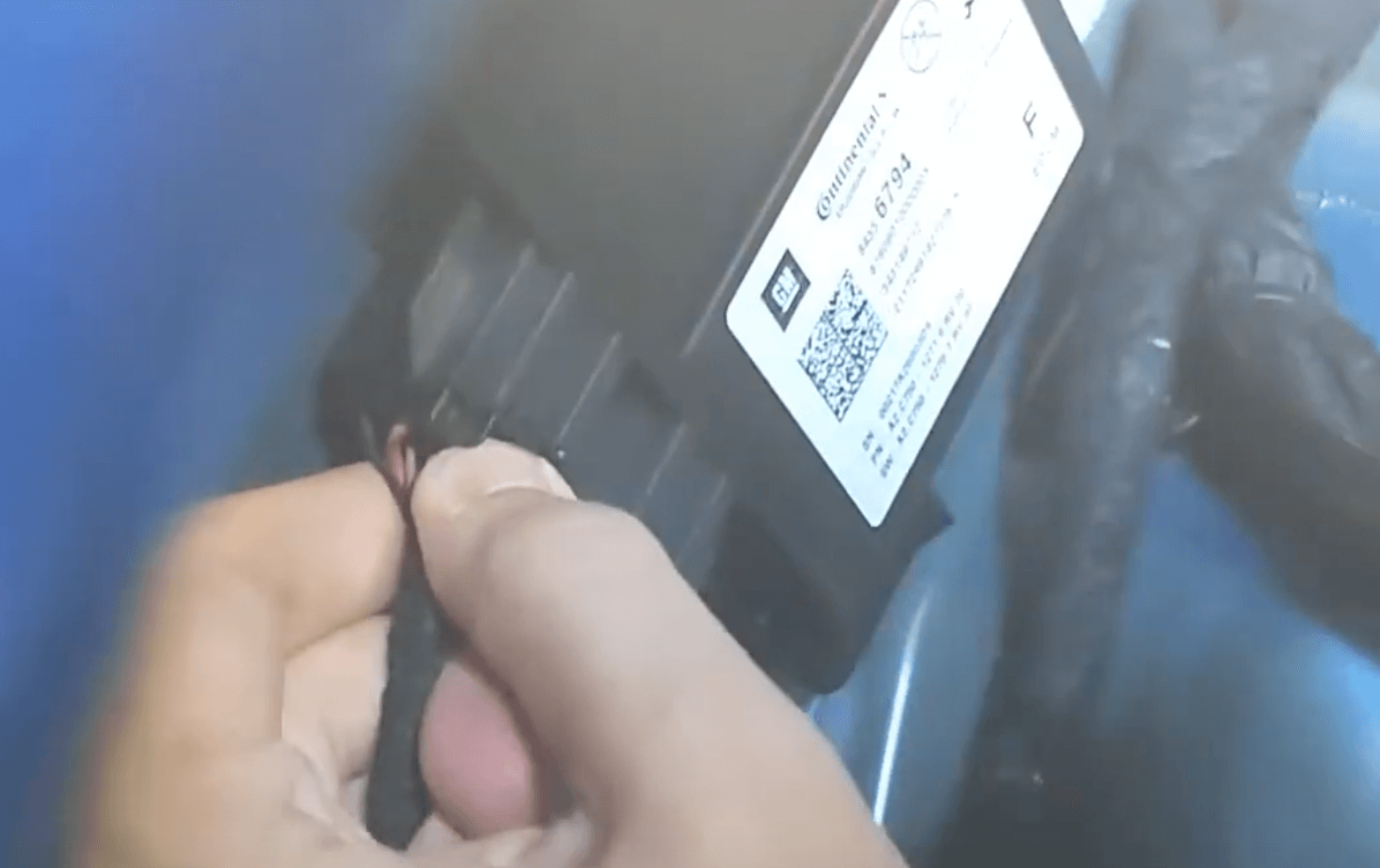
Source: Youtube - Atari Guy
Push the little tab in with your thumb and pull it out to disconnect the cable.
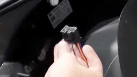
Step 19: Grab the ASCM Harness
](https://files.readme.io/0884797-Screenshot_2024-04-18_at_1.41.18_PM.png)
Source: Discord
Grab the ASCM Harness from the L&P Harness Kit.
Step 20: Plug the ASCM Harness end
Find this end of the ASCM Harness and plug it into the top port of the car's ASCM.
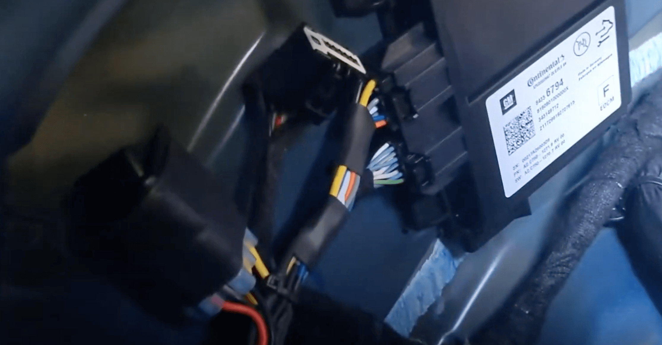
Source: Youtube - Atari Guy
When you plug in the ASCM Harness into the slot it should look like the above. The previous car cable that was disconnected should be near the ASCM Harness.
Step 21: Switch on "OP"
](https://files.readme.io/37bb466-Screenshot_2024-04-18_at_8.05.20_PM.png)
Source: Discord
Make sure the switch on the ASCM Harness is on "OP".
Step 22: Plug car connector into ASCM Harness
Source: Youtube - Atari Guy
Grab the nearby car connector that used to be in the ASCM and plug that into the other side of the ASCM Harness. There should be a cable that is part of the ASCM Harness that connects with the original car's connector.
Step 23: Put fuse #19 back in original spot
Source: Dauv
After connecting the ASCM harness, put fuse #19 back into its original place as seen above. After, fuse #19 is back, put the top cap of the fuse box back on.
Step 24: Route the long 2-pin connector cable
](https://files.readme.io/c2e8f9e-Screenshot_2024-04-18_at_7.58.40_PM.png)
Source: Discord
On the ASCM Harness, there should be a long 2-pin connector cable that has not yet been connected. This cable will be running from the ASCM to the front of the car connecting near the driver OBD-II port.
Different wire routing options
The main ones seem to be:
- Routing through the above headliner
- Routing below near floor liner (refer to 5:10 in video from Atari Guy)
Have a better option that is easier and safer? Give me a ping and lets chat. If the suggestion makes sense I will add it in. I'm always looking for better ways to go about cable management, and for an install like this, everyone currently has different preferences.
Each option has its pros and cons, do some online research on how to best route a wire from the trunk to the front dash. You can look up how other people have installed dash cams, audio systems, or other aftermarket installs that require routing cables. Researching your specific car model online will also give you a better picture of what safety features your car may have to avoid routing cables in a way that would prevent your car from deploying its safety features. Asking the community on Discord can give you a feel of what most people are doing.
Be cautious of side curtain airbags when routing through certain places of your car. Follow best practices when working with airbags to prevent injuries. The north star of cable routing should always be the one that does not negatively affect your vehicle's safety features.
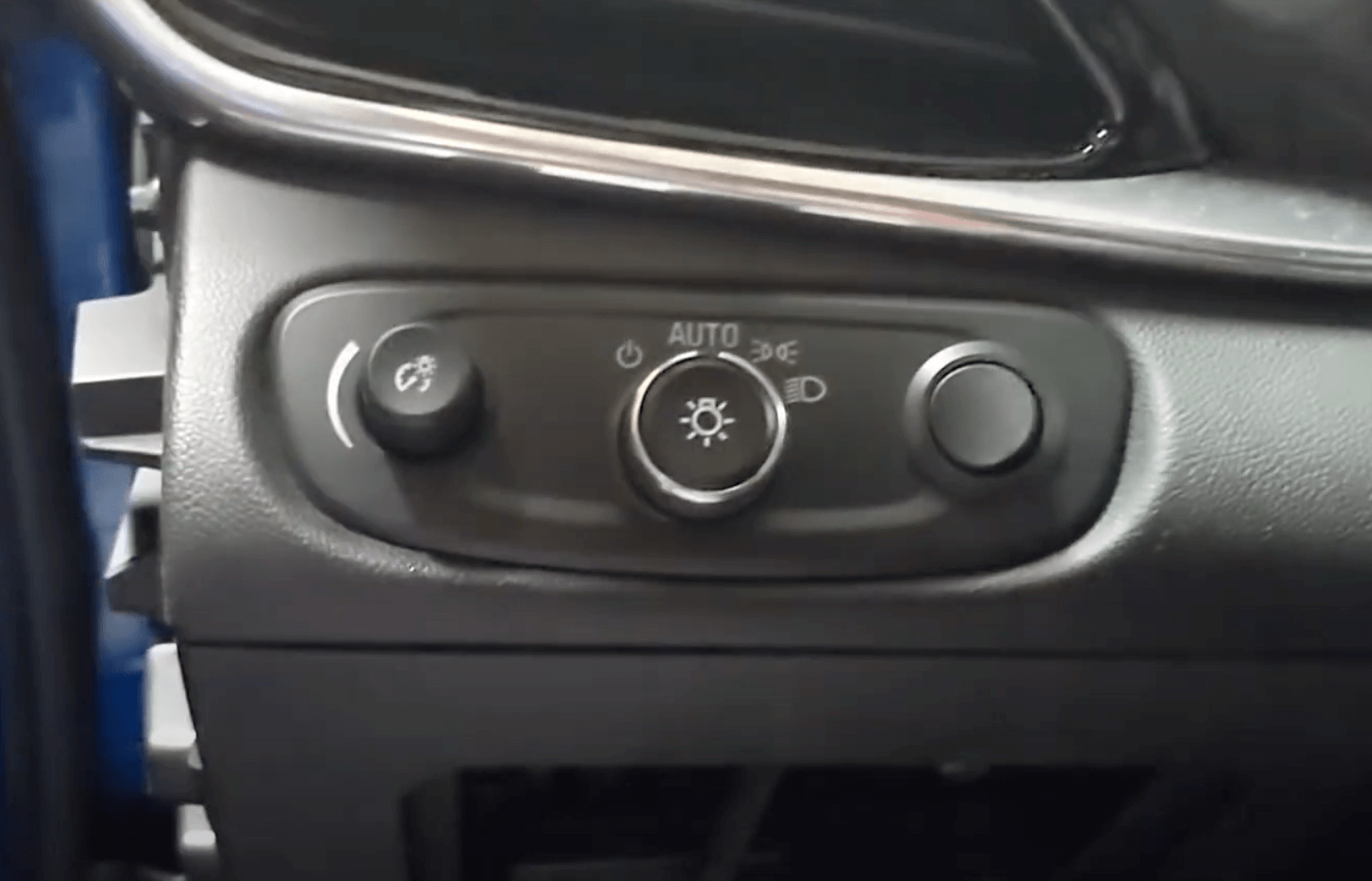
GM Lightswitch
In this section, we will install this GM light switch that is part of the L&P Harness kit. The switch shown below lets you choose between going on stock or activating the comma device.
](https://files.readme.io/9aa3287-Screenshot_2024-04-18_at_5.23.34_PM.png)
Source: Lee & Paulding
Switch functions:
- Switch from ACC to OP at any speed
- Switch Position 1 = ACC
- Switch Position 0 = Nothing (rest position)
- Switch Position 2 = OP (OBD2A does not work in position 2)
Note: Forward Collision Warning lamp will be very angry if switched while ACC is engaged
Note: Switching from OP to ACC, will only allow re-engagement of ACC after vehicle speed reaches 0mph
Note: If the switch is left in position 2 while parked, Panda and EON will continue to receive power(good for Panda auto flashing)
Step 25: Remove left panel
![Source: Youtube - [WatchJRGo]](https://files.readme.io/b6f1f5a-Screenshot_2024-04-18_at_10.13.38_PM.png)
Source: Youtube - WatchJRGo
First, remove the left panel. The panel should pop out if you use your fingers to peel it towards the door. Refer to the video time 7:42 where he removes the panel.
Step 26: Remove side screw
![Source: Youtube - [WatchJRGo]](https://files.readme.io/bd12b62-Screenshot_2024-04-18_at_10.17.27_PM.png)
Source: Youtube - WatchJRGo
The screw on the side should be a 7mm screw. Remove the screw and place the screw in a safe place.
Step 27: Removing fuse box panel
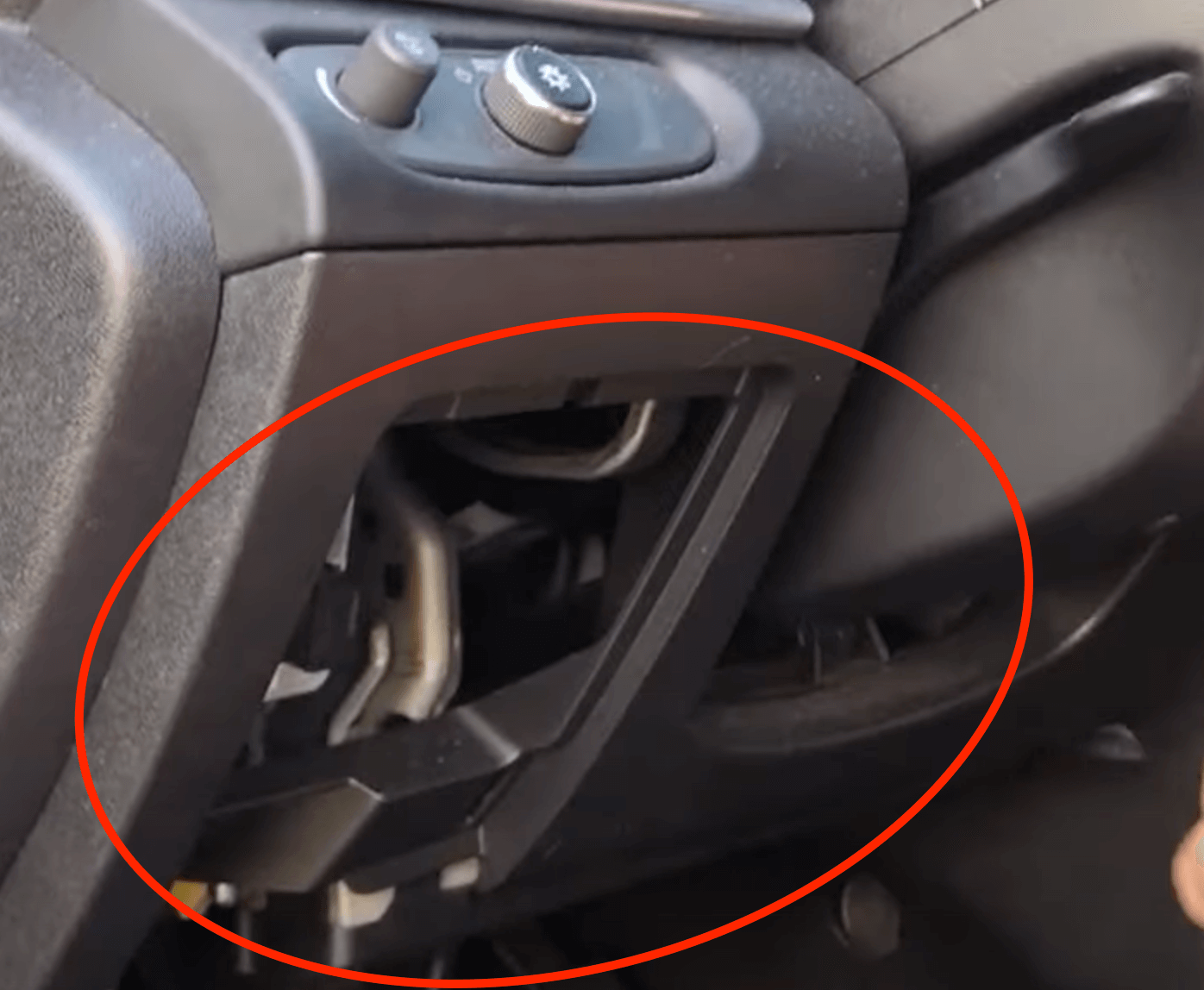
Look for the fuse box panel in the dash under the steering wheel. Use your hands to pop off the fuse box panel. The above shows the dash without the fuse box panel.
Step 28: Remove the section with the stock GM light switch
![Source: Youtube - [WatchJRGo]](https://files.readme.io/bc4b37d-Screenshot_2024-04-18_at_10.31.42_PM.png)
Source: Youtube - WatchJRGo
- Pull out this section after removing the screws holding it down. There should only be one 7mm screw on the left side from the previous step. If any other screws are holding it down, please ping me so I can revise this step.
- For more context of this removal fo to the timestamp 7:55 of the WatchJRGo video
Step 29: Disconnect cable from stock GM light switch
Source: Youtube - Paul's Place
Disconnect cable that is plugged into the back of the stock GM light switch
Step 30: Push pin to release stock GM light switch
![Source: Youtube - [WatchJRGo]](https://files.readme.io/4f01060-Screenshot_2024-04-18_at_11.09.42_PM.png)
Source: Youtube - WatchJRGo
Using a flathead screwdriver or something similar from the trim tool set, turn the plastic section so the bottom is exposed. Look for the clip that is holding down the GM light switch section, and apply pressure to release the clips. Refer to the video at timestamp 8:14.
Step 31: Replace with L&P GM light switch
Source: Lee & Paulding
Put the L&P GM light switch in the place of the stock one that came with the car. It should slide in and clip into the plastic part.
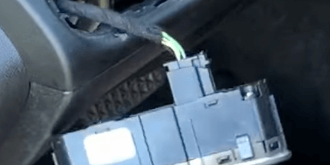
Step 32: Place the 3-pin connector cable into the dash
](https://files.readme.io/7f8d559-Screenshot_2024-04-18_at_11.25.45_PM.png)
Source: Youtube - WatchJRGo
Place the 3-pin connector cable from the L&P GM light switch into the dash where the red circle is. Run the cable so it goes down towards the OBD-II port. Let this cable hang near the OBD-II port for now.
Step 33: Connect cable into the back of L&P GM light switch
](https://files.readme.io/9ea972a-Screenshot_2024-04-19_at_12.45.01_PM.png)
Source: Youtube - Paul's Place
Grab the cable that was plugged into the back of the old stock GM light switch and plug that cable into the back of the L&P GM light switch.
Step 34: Put the L&P GM light switch plastic section back
Put the L&P GM light switch plastic section back into the dash where the old GM light switch used to sit.
Step 35: Route long 2-pin connector cable into the dash
Source: Youtube - Atari Guy
- Bring the long 2-pin connector cable(from the ASCM harness) through the side of the dash.
- Run the cable down towards the OBD-II port.
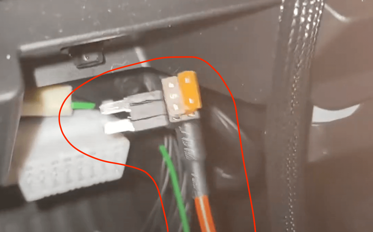
Step 36: Connect long 2-pin connector cable to L&P OBD-II splitter
Source: Discord
You should now have access near the OBD-II port to the cable circled in red. Connect this 2-pin connector cable to the other 2-pin connector cable in the dash from the L&P OBD-II splitter.
](https://files.readme.io/21172f9-Screenshot_2024-04-19_at_1.54.47_PM.png)
Source: Youtube - Atari Guy
The black cable is the long 2-pin connector from the ASCM, and the green cable in the image(color may vary) should be the 2-pin connector from the L&P OBD-II splitter.
The 2-pin connector from the L&P OBD-II splitter has a different end. The other end is a fuse tap wire. For now, ignore this other end.
Step 37: Remove stock OBD-II port
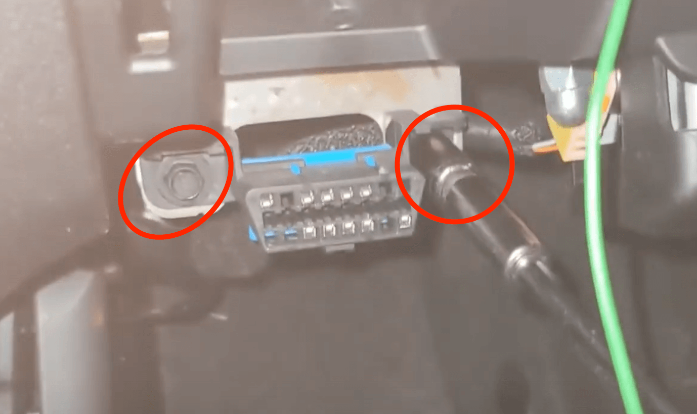
Source: Youtube - Atari Guy
- Grab a socket wrench/tool to unscrew the 7mm screw that is holding the OBD-II. Put screws in a safe place.
- Let the stock OBD-II port hang for now.
Step 38: Connect the female end of the L&P OBD-II splitter
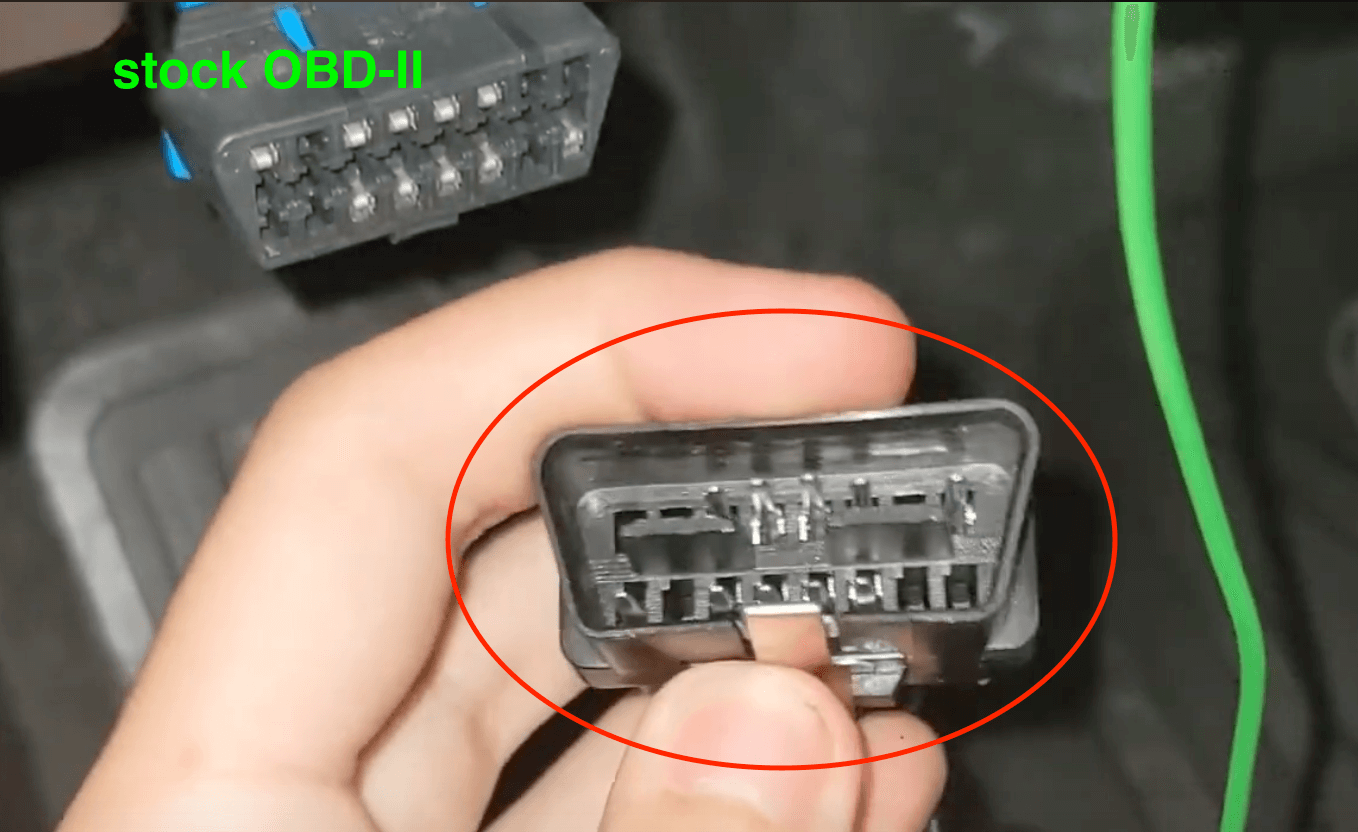
Source: Youtube - Atari Guy
Connect the male end of the L&P OBD-II splitter shown in the red circle into the now hanging stock OBD-II port.
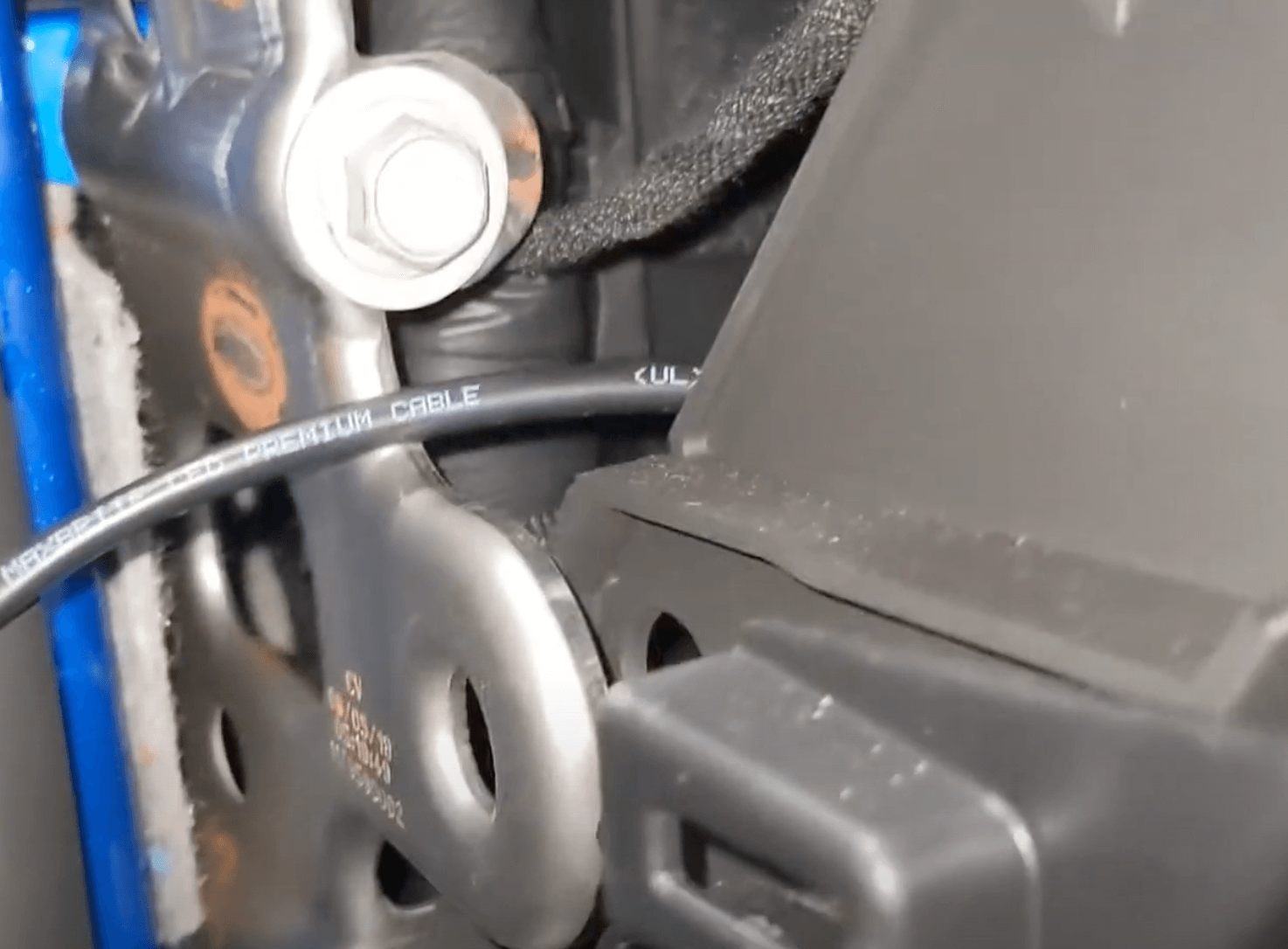
Step 39: Screw L&P OBD-II plate
Source: Youtube - Atari Guy
- Use the 7mm screws to bolt the L&P OBD-II plate into where the old stock OBD-II port used to sit. This OBD-II port will be the extra port that will not be used for the comma device. The OBD-II plate will be part of the OBD-II splitter
- There will be another female OBD-II port that is part of the OBD-II splitter from L&P. Leave this hanging for now.
Step 40: Remove F36 fuse
Source: Youtube - Paul's Place
Remove the F36 Fuse which is underneath the R1 fuse. The diagram above can be found behind the plastic fuse box cover of the dash.
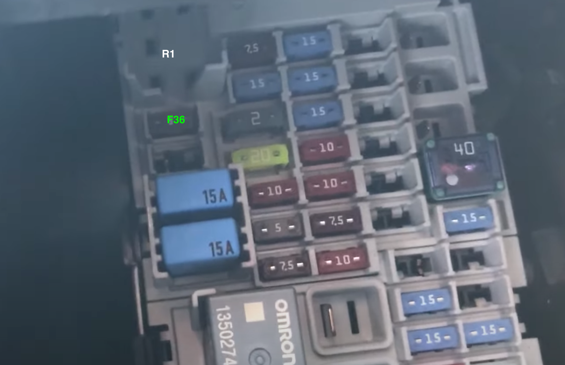
Source: Youtube - Paul's Place
Grab needle nose pliers to remove the F36 fuse from the fusebox. As seen above the F36 fuse is where the neon green text is located.
Step 41: Route fuse tap wire
Source: Youtube - Atari Guy
Grab the fuse tap wire and bring it up through the dash to reach the fuse box located above the OBD-II port.
Step 42: Plug in fuse tap wire into F36
](https://files.readme.io/ee730af-Screenshot_2024-04-19_at_3.41.13_PM.png)
Source: Dauv
Plug in fuse tape wire into F36 as seen in the red circle. Fuse tap wire may vary with L&P Harness kits.
Step 43: Connect the 3-pin connector
Source: Youtube - Atari Guy
Grab the 3-pin connector that is from the L&P GM switch and connect this cable to the 3-pin connector from the L&P OBD-II splitter.
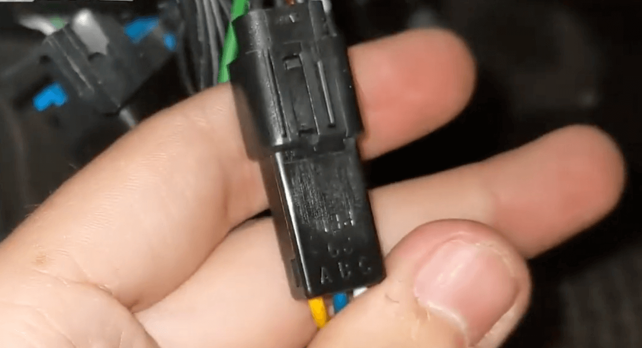
Step 44: Connect the OBD-II connector
](https://files.readme.io/b16b185-Screenshot_2024-04-19_at_9.51.06_PM.png)
OBD-II connector - Source: Discord
Plug the OBD-II connector into the hanging female OBD-II port from the L&P OBD-II Splitter. The OBD-II connector comes with the OBD-II Harness from comma.
Step 45: Connect long OBD-C cable
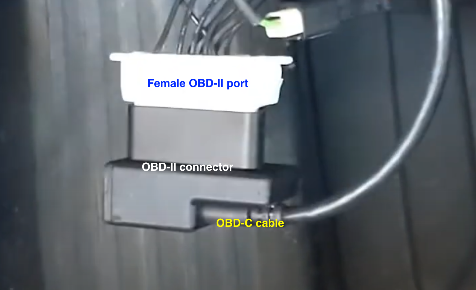
Source: Youtube - Atari Guy
Connect the long OBD-C cable to the OBD-II connector. The above photo shows the OBD-C cable connected to the OBD-II connector which is connected to the hanging female OBD-II.
Cable Management Guide
This section will review options for routing the long OBD-C cable to reach your comma device on the windshield. If there are cleaner, easier routing solutions than this, give me a ping!
Routing Diagram
](https://files.readme.io/b00c53f-IMG_0516_1.jpg)
Source: Cars
| Color | Description |
|---|---|
| White Box | This is the general location of where the OBD-C cable connects w/OBD-II connector. |
| Yellow Line | The OBD-C cable running through the fuse box area traveling left toward the driver door. |
| Yellow Circle | There should be a removable plastic panel that the OBD-C cable can come out of. Run the OBD-C cable through the cracks of this panel. |
| Blue Line | the part of the cable will run under the weather stripping near the door until it gets to the A-pillar. Once you reach the A-pillar, route the cable to reach the position of the red line. The cable should not cross on top of the airbag! |
| Red Line | This part of the cable should sit between the windshield and the airbag. Find factory wiring and route the cable where the factory wires are running. DO NOT put wire on top of the airbag! |
| Pink Line | This part of the cable will be tucked underneath the edge of the headliner. |
| Pink Circle | USB-C coupler that is included when you buy the OBD-II harness. This USB-C coupler will connect the 1.5ft right-angle OBD-C cable to the long OBD-C cable that comes with the OBD-II Harness from comma. |
| Green Line | The 1.5ft right angle OBD-C cable that is included when you buy a comma 3X. |
Step 1: Grab the OBD-C cable
- Grab the other end of the OBD-C cable NOT connected to the Harness Box/relay
- Don't put the USB-C coupler until the cable is closer to the comma device
Step 2: Bring wire through the fuse box
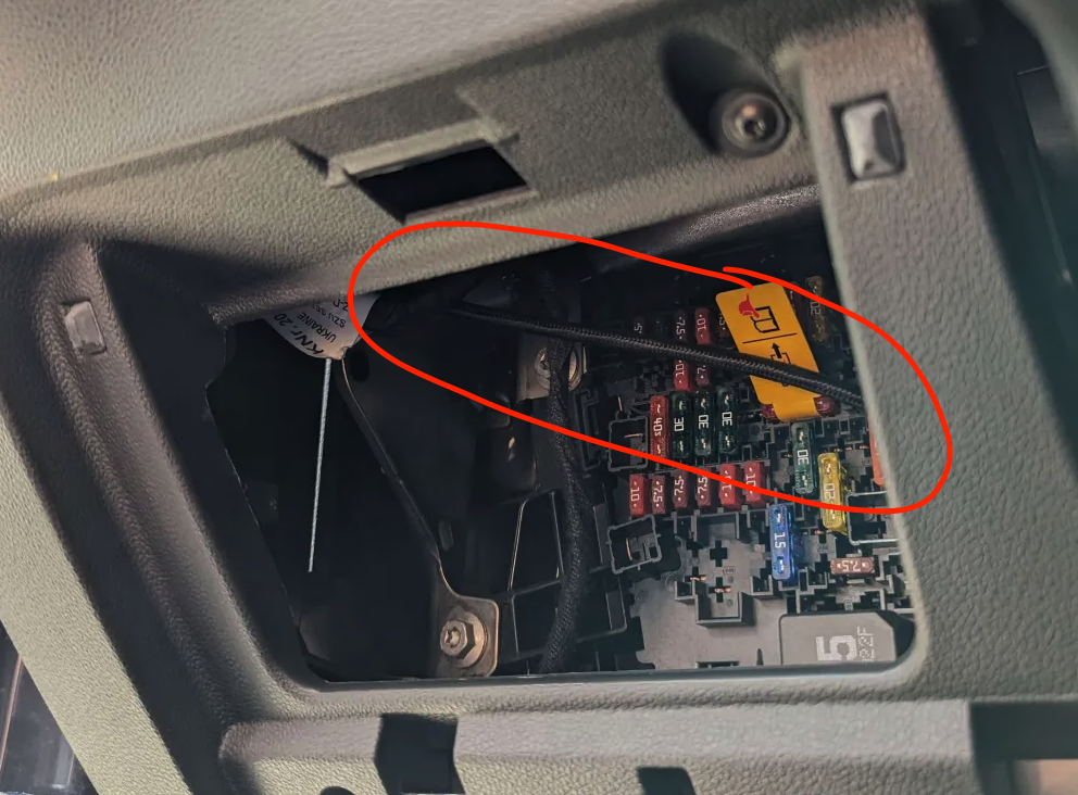
- Bring the end of the OBD-C cable through the fuse box
- There should be another opening on the other side for the cable to slip through
Step 3: Slip the cable through the back crack
- Grab the OBD-C cable and push it through the back crack.
Step 4: Ignore the previous 2 steps IF...
](https://files.readme.io/adc5402-IMG_0516_1_copy.jpg)
Source: Cars
- If your car does not have the side opening shown in the previous step, skip those steps
- Route the cable(purple line) underneath the fuse box then up to the bottom of the blue line as shown above. The cable can be tucked into the weather stripping near the door.
- If you successfully did the previous 2 steps then ignore this step
Step 5: Removing A-pillar
It's important not to restrict the airbag in case of an accident. Do not place wires on top of the airbag or in any way that would restrict it.
⚠️ Make sure to read A-pillar Wire Routing 🔗. This is an essential step to ensure the wire is routed in the safest way possible. After reading A-pillar Wire Routing return to this guide and proceed to the next step.
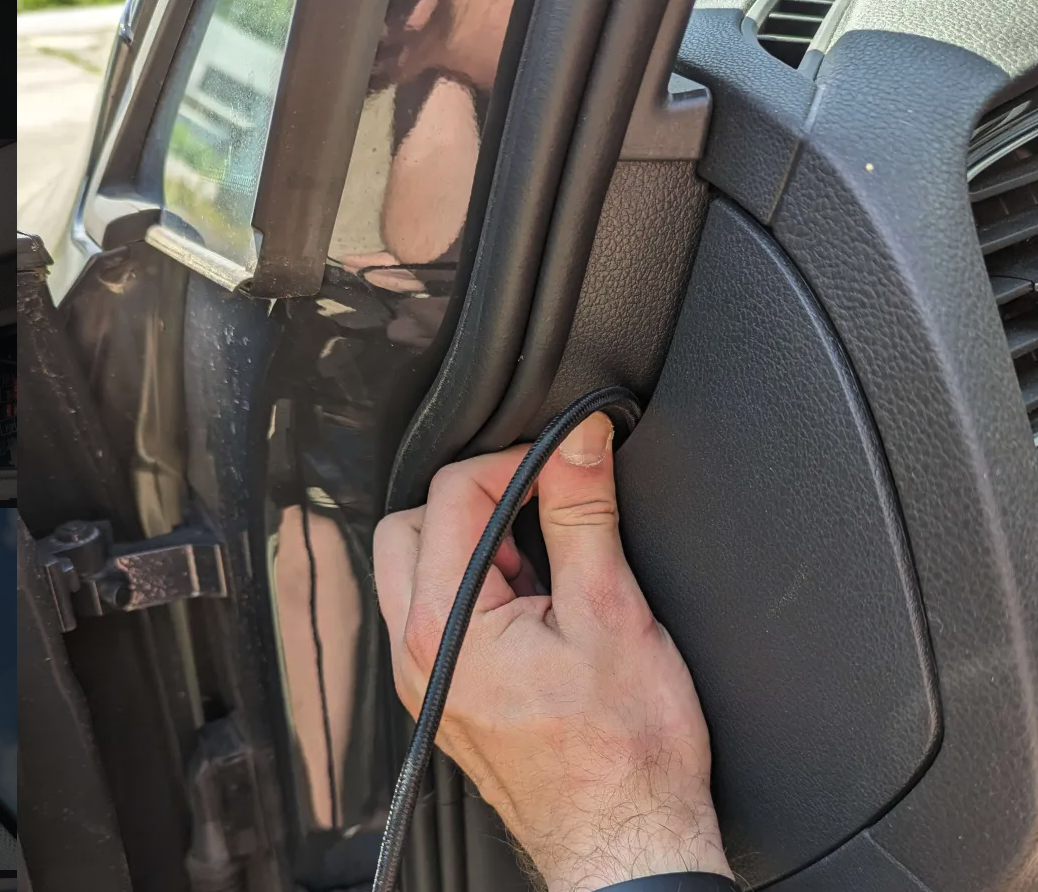
Step 6: Tuck the remaining wire
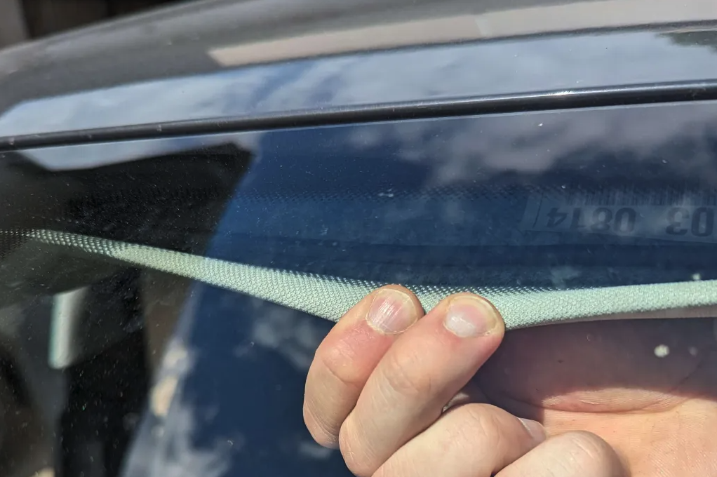
Last time you will be tucking in wires. This part is the pink line from the diagram. Peel open the edge of the headliner and tuck the wire in. Tuck the wire across the windshield until it reaches the comma device.
Step 7: Grab USB-C Coupler
Connect the USB-C coupler to the end of the OBD-C cable.
Step 8: Connect comma Device Cable
- Grab the included cable that came with the comma device and plug the angled end into the device.
- Grab the other end and plug that into the OBD-C cable that has the USB-C coupler
Step 9: Turn On Car
](https://files.readme.io/90613cb-IMG_0516_1_copy.jpg)
Source: Cars
When you turn on the car the comma device should power up automatically. Your wire routing should look like the above diagram. The yellow and purple line shows the 2 options for that area.
Step 10: Clean up
Put back all trim and screws that may have been removed. For a quick reference on what needs to be put back go to the time stamp 9:20 in the video from Atari Guy.
Step 11: Give yourself a high-five! 🏁
Nice job! You have installed the necessary hardware to use your comma device with an OBD-II harness! Continue to the next part where you learn how to install software into your comma device.
GitHub Community Wiki
Check out the Community Wiki for GM.
Have feedback?
If any steps were incorrect or could have better pictures/descriptions for that step, send them my way. Give me a ping on Discord and if the suggestions make sense I will update the guide.